HotplateReflow
My First reflow soldering attempt was a costly failure. I used too much heat and burnt the boards, along with the components. Before burning more money on my next project, I thought I'd experiment with some rubbish PCB's and random capacitors.
Equipment
- A 1800W hotplate. $19 from Sams Warehouse.
- A syringe of no-clean solder paste from Jaycar
- 200 x 200 x 5mm aluminium sheet. $13 from Capral
- Infrared thermometer
The aluminium sheet sits between the hotplate and the PCB with the goal of evenly distributing heat all over the PCB. It needs to be thick enough to remain structually intact (i. perfectly flat) when heated.
Reflow Profile 1
Heat the boards at full-power until the solder starts to melt, then turn the hotplate off. Leave the PCB where it is until cooled.
Observations
- Solder paste applied to each area of the board melted simultaneously. The thick aluminium plate worked well to distribute the heat evenly.
- The hotplate was turned off at around 200°C, but continued to rise until 255°C. There was a loud "pop", which I assume was some burning flux.
- After 20 minutes the aluminium plate and PCB were still too hot to touch.
- After cooling the silk layer on both sides of the board was discoloured, and the tinned pads appeared "patchy".
Reflow Profile 2
Heat the boards at full-power until 175°C, then turn the hotplate off. Wait 10 seconds after the solder starts to melt, then push the PCB off the hotplate/aluminium with a wooden pencil and let it cool down.
Observations
- Solder paste applied to each area of the board melted simultaneously. The thick aluminium plate worked well to distribute the heat evenly.
- The solder (leaded) started to melt at 190°C.
- 10 seconds after the melting started, the board was 205°C and removed from the hotplate.
Results
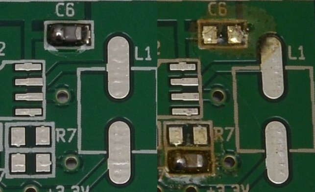
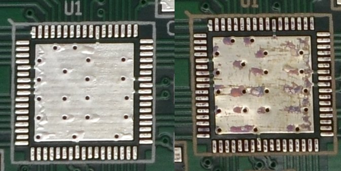
In the following photos "Reflow Profile 2" is on the left, and is clearly the better result. Ignore the excessive amount of solder used on the capicitors - I once again applied way too much solder paste.