Macintosh VGA: Difference between revisions
mNo edit summary |
|||
| Line 96: | Line 96: | ||
Sense Pins: Connect pin 7 to pin 10 for VGA. Leave pin 4 not connected. | Sense Pins: Connect pin 7 to pin 10 for VGA. Leave pin 4 not connected. | ||
== DIY Adapter == | |||
[http://www.codesrc.com/images/macvga.jpg http://www.codesrc.com/images/macvga_small.jpg] | |||
I designed and built a custom circuit board, as pictured above. This solution is works really well. | |||
[http://www.codesrc.com/files/macvga_640x480.zip Download] the schematics, PCB layout, and gerber files. The board was designed using the free [www.geda-project.org/ gEDA] tools. | |||
Parts Required: | |||
* PCB. I ordered mine from [http://smart-prototyping.com/ Smart Prototyping]. The board is less than the 5cmx5cm. The <code>gerber/</code> directory within the .zip file contains all files in the format expected by Smart Prototyping. | |||
* DA-15 male socket. DigiKey part 609-4005-ND (FCI 10090097-P154VLF). | |||
* DE-15 female socket. DigiKey part 609-2802-ND (FCI ICD15S13E6GV00LF). | |||
== Build Attempt 1 == | == Build Attempt 1 == | ||
| Line 159: | Line 171: | ||
Despite poor in construction, the cable does work perfectly! (at least with my LCD monitor. YMMV). | Despite poor in construction, the cable does work perfectly! (at least with my LCD monitor. YMMV). | ||
== References == | == References == | ||
Revision as of 12:04, 17 January 2014
The Apple Macintosh LCIII provides video via a DA15 connector. The LCIII provides VGA-compatible signals, but uses a different connector and pinout than standard VGA.
The information below probably applies to the entire Apple LC series and equivalents.
VGA Monitor Compatibility
Most VGA monitors will be able to display the 640x480 signal sent by the Mac. To check if your monitor is compatible, ensure it can display a hsync of 31.469 kHz, and vsync 59.94 Hz.
eg. A brand new (as of Sep 2011) Dell ST2420L 24" LED-backlit LCD monitor is advertised as supporting a "Horizontal scan range" of 30 kHz to 83 kHz, and a "Vertical scan range" of 56 Hz to 76 Hz. This monitor will support the Mac hsync and vsync signals, as both are within their respective supported ranges.
Mac compatibility
A VRAM upgrade module is required to enable 16bit colour when running at VGA resolutions on the LCIII. Up to 8-bit (256) colour is supported without the VRAM upgrade.
Sense Pins
The Mac uses 3 pins on the video connector to determine the type of monitor attached. Connecting pins 10 and 7 informs the Mac that a VGA monitor is attached.
Some commercial Mac video -> VGA adapters provide DIP switches that allow setting these sense pins to emulate a specific Apple monitor. eg. The Apple 12" RGB Monitor uses sense code "0 1 0". There is little point in experimenting with the sense pins, as most modern VGA monitors won't display the oddball resolutions of these legacy displays.
eg. The Apple 12" RGB Monitor supports a resolution of 512x384 with a hsync of 24.48 kHz. This hsync value is well below the supported range of modern VGA monitors.
The Apple 16" RGB Monitor supports a resolution of 832x624, with hsync and vsync signals within the acceptable range of modern monitors. I suspect most LCD monitors would reject this resolution anyway. I have no need to run Mac software which requires the higher resolutions, so I won't bother testing this mode.
Connectors
The LCIII provides a female DA-15 connector for video signals. A standard VGA monitor cable is male DE-15, which is commonly (incorrectly) stated as DB15 or DB15HD.
Pinouts
| DA-15 (Mac) Pin | Description | DE-15 (VGA) equivalent Pin |
|---|---|---|
| 1 | Red ground | 6 |
| 2 | Red signal | 1 |
| 3 | CSYNC | Not connected |
| 4 | Monitor sense signal 0 | |
| 5 | Green signal | 2 |
| 6 | Green ground | 7 |
| 7 | Monitor sense signal 1 | |
| 8 | Not connected | Not connected |
| 9 | Blue signal | 3 |
| 10 | Monitor sense signal 2 | |
| 11 | CSYNC and VSYNC ground | 10 |
| 12 | VSYNC | 14 |
| 13 | Blue ground | 8 |
| 14 | HSYNC ground | 5 |
| 15 | HSYNC | 13 |
| Shell | Shield ground | Cable braid |
Sense Pins: Connect pin 7 to pin 10 for VGA. Leave pin 4 not connected.
DIY Adapter
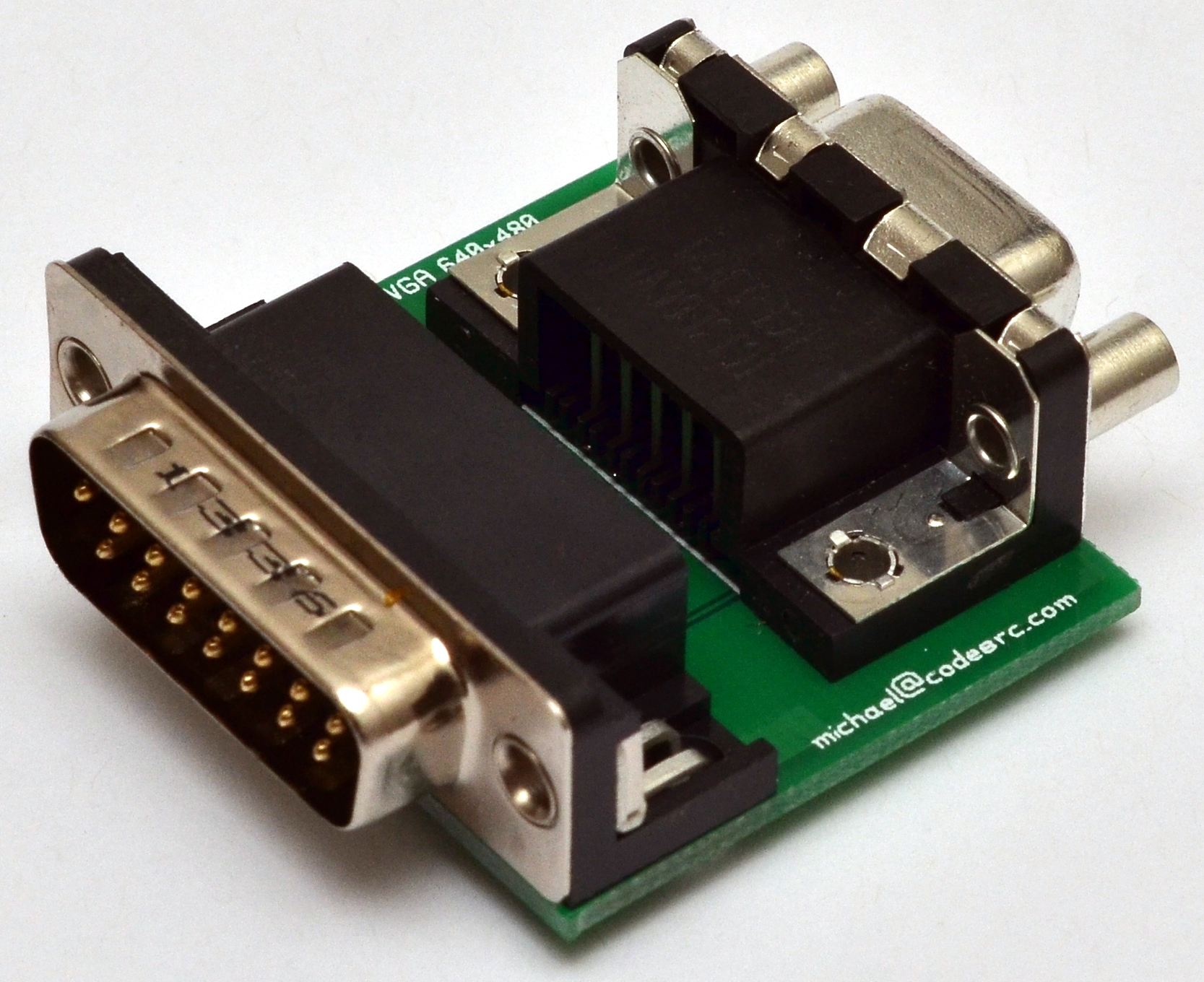
I designed and built a custom circuit board, as pictured above. This solution is works really well.
Download the schematics, PCB layout, and gerber files. The board was designed using the free [www.geda-project.org/ gEDA] tools.
Parts Required:
- PCB. I ordered mine from Smart Prototyping. The board is less than the 5cmx5cm. The
gerber/directory within the .zip file contains all files in the format expected by Smart Prototyping. - DA-15 male socket. DigiKey part 609-4005-ND (FCI 10090097-P154VLF).
- DE-15 female socket. DigiKey part 609-2802-ND (FCI ICD15S13E6GV00LF).
Build Attempt 1
My first attempt at a VGA adapter involved the use of a "donor" VGA cable, to which I soldered the required DA-15 plug. I would recommend others NOT use this method. I found that cheap VGA cables use the smallest possible conductors, and that stripping/soldering such small wires is very difficult. In particular, the ground return wires were impossible to separate from the signal wire without snapping it. I ended up with the following connections (ie. I connected all the grounds together, then soldered it to the outer braid of the cable, thus completely ignoring the ground-return wires within the cable).
| DA-15 (Mac) Pin | Description | DE-15 (VGA) Pin |
|---|---|---|
| 1 | Red ground | Cable braid |
| 2 | Red signal | 1 |
| 5 | Green signal | 2 |
| 6 | Green ground | Cable braid |
| 7 | Monitor sense signal 1 | Looped back to Pin 10 on the Mac side |
| 9 | Blue signal | 3 |
| 10 | Monitor sense signal 2 | Looped back to Pin 7 on the Mac side |
| 11 | CSYNC and VSYNC ground | Not connected |
| 12 | VSYNC | 14 |
| 13 | Blue ground | Cable braid |
| 14 | HSYNC ground | Cable braid |
| 15 | HSYNC | 13 |
| Shell | Shield ground | Not connected |
Despite poor in construction, the cable does work perfectly! (at least with my LCD monitor. YMMV).
References
- Details on VGA timing, sense pins and the DA15 connector pinouts and can be found in the Apple developer notes.
- Read about D-subminature connectors and understand the confusion surrounding DE15 and DB15 before purchasing incorrect parts.
- DA15 monitor -> VGA pinout.