SCSI2SD UserManual: Difference between revisions
m Expanding --blocks option |
|||
| (12 intermediate revisions by the same user not shown) | |||
| Line 1: | Line 1: | ||
NOTE: Unless noted otherwise, descriptions herein refer to features of firmware version 4.2.4 and later. | |||
== Important Notes == | == Important Notes == | ||
Do not allow the underside of the [[SCSI2SD]] come into contact with any conductive surfaces. Doing so may result in damage to the SCSI2SD, damage to your computer's power supply, or fire. | '''WARNING''': Do not allow the underside of the [[SCSI2SD]] come into contact with any conductive surfaces. Doing so may result in damage to the SCSI2SD, damage to your computer's power supply, or fire. | ||
'''WARNING: Do not power the board using 12V!''' This usually happens by mistake when people make custom power cables for use in samplers without standard drive molex connections. It's very easy to switch the positions of the 5V and 12V wires. The SCSI2SD doesn't require 12V at all, so leave the wire out completely. If you do supply more than 5V, a new hole will appear in the main chip (Cypress PSoC 5lp) and the magic smoke will escape. The SCSI2SD will not work again until the main chip is replaced. | |||
== Power == | == Power == | ||
5V power can be supplied by a standard disk drive power connector | 5V power can be supplied by either: | ||
* The SCSI cable, if the SCSI host supplies sufficient terminator power (V5/V6) | |||
* a floppy-style power connector (V6) | |||
* standard disk drive power connector (V3/v4/v5) | |||
* a micro-usb cable. | |||
It is safe to connect both multiple of power simultaneously. | |||
== Active Terminator == | == Active Terminator == | ||
The terminator can be disabled by removing the 2 resistor packs. When re-inserting the resistor packs, be sure to align the printed dot on the resistors with the board markings. | === V6.0 boards === | ||
The terminator is enabled via software configuration using the scsi2sd-util6 tool. | |||
=== V5.0 boards === | |||
The terminator can be disabled by removing the 2 resistor packs. | |||
The markings on the resistor pack should be at the Molex drive power connector end. | |||
The <code>J3TERMPWR</code> jumper is not used on these boards. Due to the more efficient power supply (switching regulator as opposed to linear reegulator) USB power is sufficient to run run the terminator. | |||
=== Pre-V5.0 boards === | |||
The terminator can be disabled by removing the 2 resistor packs. | |||
When re-inserting the resistor packs, be sure to align the printed dot on the resistors with the board markings. | |||
Most SCSI host controllers provide the power required to run the terminators via the 50-pin cable. For those controllers that fail to provide termination power, the <code>J3TERMPWR</code> jumper may be closed to provide such power. | Most SCSI host controllers provide the power required to run the terminators via the 50-pin cable. For those controllers that fail to provide termination power, the <code>J3TERMPWR</code> jumper may be closed to provide such power. | ||
| Line 12: | Line 34: | ||
Providing termination power via J3 only works when powered via a standard disk drive power connector. A USB cable cannot provide sufficient current, and so the USB 5V line is not connected to J3. | Providing termination power via J3 only works when powered via a standard disk drive power connector. A USB cable cannot provide sufficient current, and so the USB 5V line is not connected to J3. | ||
== | == Which micro-SD card ? == | ||
===V6 === | |||
Use a Class 10 or faster card to ensure good performance. | |||
=== V3/V4/V5 === | |||
Because SCSI2SD uses SPI to access the micro-SD card, there is little benefit to faster memory (class (10) vs. (4) or (2)). Use whatever is convenient. The common, easy-to-find | |||
class (10) cards are typically used during SCSI2SD development and testing. | |||
== Hot Swap == | |||
Requires firmware version 4.0 or above. | |||
See [[Hot Swap]] for details on modifying old SCSI2SD boards to support hot swap. | |||
== | == Updating the firmware == | ||
* Obtain the latest firmware file and scsi2sd-util utility from [http://www.codesrc.com/files/scsi2sd codesrc.com]. | |||
* Disconnect or turn off ALL sources of power from the SCSI2SD, including the USB cable. Any connected SCSI host controller or devices must be turned off. | |||
* Run the scsi2sd-util line utility. | |||
Execute permissions are required on Mac OSX and Linux: | |||
sudo chmod a+x scsi2sd-util | |||
sudo scsi2sd- | |||
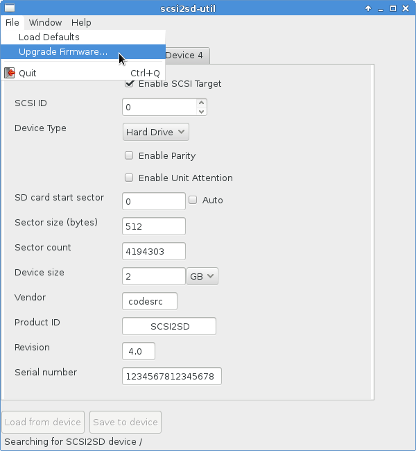
* | * Select "Upgrade Firmware" from the scsi2sd-util File menu, and select the firmware file. Click OK. | ||
* Connect the USB cable. | |||
http://www.codesrc.com/images/SCSI2SD/scsi2sd-util_upgradefirmware.png | |||
* The log window should show the device found and the firmware updated. | |||
== Defaults == | |||
If you run scsi2sd-util with the USB cable NOT connected to the SCSI2SD board, you will see the current configuration defaults. Since the procedure for upgrading firmware (above) begins that way, the default configuration values may be seen in the picture above. The default is to act as a single drive at SCSI ID 0 of size 2GB (unless the SD card capacity is smaller). | |||
In many cases, the default configuration on the board will work "out of the box", but it may not be optimal in your case. | |||
== Options == | |||
SCSI2SD supports up to 4 different SCSI ID's, each using a different section of the SD card. | |||
* "Enable Parity" refers to checking SCSI bus parity on incoming requests. For best results, set this to match your equipment. With equipment that supports SCSI bus parity generation, enabling this provides better noise/error detection and helps detect bad termination or cabling. | |||
* "Enable Unit Attention": If enabled, the SCSI Unit Attention status is sent at power on, whenever the SCSI2SD configuration is written, and when the memory card in inserted or removed. This option should be enabled if you plan to "hot swap" microSD cards. | |||
* Vendor, Product ID, Revision, and Serial number may be changed if desired. | |||
* Device size is the desired virtual size This allows, say, a 16GB micro-SD card to be used even if the equipment has a 2GB disk size limit. The value used is the lower of the configured value and the actual microSD card size. | |||
NOTE: At the moment (through firmware 4.2.4), all configuration information is stored on the SCSI2SD board, not in the memory card. There is, thus, no removable-card-specific configuation. | |||
- | == Current Configuration == | ||
Using scsi2sd-util, with the USB cable connected to the SCSI2SD board, and with the log window showing that the SCSI2SD device has been detected, click [Load from device] to get the current configuration. | |||
== Changing Configuration == | |||
The SCSI2SD is configured over the USB interface. | |||
* Obtain the scsi2sd-util utility from [http://www.codesrc.com/files/scsi2sd codesrc.com]. | |||
* The following additional packages may be required on Linux: | |||
** libudev0 | |||
** libpng12 | |||
* Execute permissions are required on Mac OSX and Linux | |||
chmod a+x scsi2sd-util | |||
Root priviledges may be required on Linux: | |||
sudo scsi2sd-util | |||
* Connect the SCSI2SD via the USB cable, and then start scsi2sd-util. | |||
* Optionally, click [Load from device] to retrieve the SCSI2SD board's current configuration. | |||
* Change the values as desired. | |||
* Click [Save to device] to write the new configuration to the SCSI2SD board. The log window should show the configuration being written. | |||
Latest revision as of 03:53, 20 August 2016
NOTE: Unless noted otherwise, descriptions herein refer to features of firmware version 4.2.4 and later.
Important Notes
WARNING: Do not allow the underside of the SCSI2SD come into contact with any conductive surfaces. Doing so may result in damage to the SCSI2SD, damage to your computer's power supply, or fire.
WARNING: Do not power the board using 12V! This usually happens by mistake when people make custom power cables for use in samplers without standard drive molex connections. It's very easy to switch the positions of the 5V and 12V wires. The SCSI2SD doesn't require 12V at all, so leave the wire out completely. If you do supply more than 5V, a new hole will appear in the main chip (Cypress PSoC 5lp) and the magic smoke will escape. The SCSI2SD will not work again until the main chip is replaced.
Power
5V power can be supplied by either:
- The SCSI cable, if the SCSI host supplies sufficient terminator power (V5/V6)
- a floppy-style power connector (V6)
- standard disk drive power connector (V3/v4/v5)
- a micro-usb cable.
It is safe to connect both multiple of power simultaneously.
Active Terminator
V6.0 boards
The terminator is enabled via software configuration using the scsi2sd-util6 tool.
V5.0 boards
The terminator can be disabled by removing the 2 resistor packs.
The markings on the resistor pack should be at the Molex drive power connector end.
The J3TERMPWR jumper is not used on these boards. Due to the more efficient power supply (switching regulator as opposed to linear reegulator) USB power is sufficient to run run the terminator.
Pre-V5.0 boards
The terminator can be disabled by removing the 2 resistor packs.
When re-inserting the resistor packs, be sure to align the printed dot on the resistors with the board markings.
Most SCSI host controllers provide the power required to run the terminators via the 50-pin cable. For those controllers that fail to provide termination power, the J3TERMPWR jumper may be closed to provide such power.
Providing termination power via J3 only works when powered via a standard disk drive power connector. A USB cable cannot provide sufficient current, and so the USB 5V line is not connected to J3.
Which micro-SD card ?
V6
Use a Class 10 or faster card to ensure good performance.
V3/V4/V5
Because SCSI2SD uses SPI to access the micro-SD card, there is little benefit to faster memory (class (10) vs. (4) or (2)). Use whatever is convenient. The common, easy-to-find class (10) cards are typically used during SCSI2SD development and testing.
Hot Swap
Requires firmware version 4.0 or above.
See Hot Swap for details on modifying old SCSI2SD boards to support hot swap.
Updating the firmware
- Obtain the latest firmware file and scsi2sd-util utility from codesrc.com.
- Disconnect or turn off ALL sources of power from the SCSI2SD, including the USB cable. Any connected SCSI host controller or devices must be turned off.
- Run the scsi2sd-util line utility.
Execute permissions are required on Mac OSX and Linux:
sudo chmod a+x scsi2sd-util
- Select "Upgrade Firmware" from the scsi2sd-util File menu, and select the firmware file. Click OK.
- Connect the USB cable.
- The log window should show the device found and the firmware updated.
Defaults
If you run scsi2sd-util with the USB cable NOT connected to the SCSI2SD board, you will see the current configuration defaults. Since the procedure for upgrading firmware (above) begins that way, the default configuration values may be seen in the picture above. The default is to act as a single drive at SCSI ID 0 of size 2GB (unless the SD card capacity is smaller).
In many cases, the default configuration on the board will work "out of the box", but it may not be optimal in your case.
Options
SCSI2SD supports up to 4 different SCSI ID's, each using a different section of the SD card.
- "Enable Parity" refers to checking SCSI bus parity on incoming requests. For best results, set this to match your equipment. With equipment that supports SCSI bus parity generation, enabling this provides better noise/error detection and helps detect bad termination or cabling.
- "Enable Unit Attention": If enabled, the SCSI Unit Attention status is sent at power on, whenever the SCSI2SD configuration is written, and when the memory card in inserted or removed. This option should be enabled if you plan to "hot swap" microSD cards.
- Vendor, Product ID, Revision, and Serial number may be changed if desired.
- Device size is the desired virtual size This allows, say, a 16GB micro-SD card to be used even if the equipment has a 2GB disk size limit. The value used is the lower of the configured value and the actual microSD card size.
NOTE: At the moment (through firmware 4.2.4), all configuration information is stored on the SCSI2SD board, not in the memory card. There is, thus, no removable-card-specific configuation.
Current Configuration
Using scsi2sd-util, with the USB cable connected to the SCSI2SD board, and with the log window showing that the SCSI2SD device has been detected, click [Load from device] to get the current configuration.
Changing Configuration
The SCSI2SD is configured over the USB interface.
- Obtain the scsi2sd-util utility from codesrc.com.
- The following additional packages may be required on Linux:
- libudev0
- libpng12
- Execute permissions are required on Mac OSX and Linux
chmod a+x scsi2sd-util
Root priviledges may be required on Linux:
sudo scsi2sd-util
- Connect the SCSI2SD via the USB cable, and then start scsi2sd-util.
- Optionally, click [Load from device] to retrieve the SCSI2SD board's current configuration.
- Change the values as desired.
- Click [Save to device] to write the new configuration to the SCSI2SD board. The log window should show the configuration being written.