SCSI2SD old: Difference between revisions
m Michael moved page SCSI2SD to SCSI2SD old: This page is now for historical reference only, and does not necessarily describe the device as-built. |
|||
| (12 intermediate revisions by the same user not shown) | |||
| Line 1: | Line 1: | ||
A device that presents a | A device that presents a an SD Card as a Direct Access device to a SCSI controller. | ||
| Line 20: | Line 20: | ||
** Note that this drive is SCSI-2, single-ended, <strong>active</strong> termination. | ** Note that this drive is SCSI-2, single-ended, <strong>active</strong> termination. | ||
* The device shall optionally provide active termination, enabled and disabled via a jumper. | * The device shall optionally provide active termination, enabled and disabled via a jumper. | ||
* The device shall | * The device shall provide termination power. | ||
** Some Macs don't provide termination power. See [http://docs.info.apple.com/article.html?artnum=6159] | ** Some Macs don't provide termination power. See [http://docs.info.apple.com/article.html?artnum=6159] | ||
** This enables "loopback" testing of the device without connecting to a SCSI bus. | |||
* The device shall optionally check parity, enabled and disabled via a jumper. | * The device shall optionally check parity, enabled and disabled via a jumper. | ||
** Some Amiga SCSI controllers don't provide parity. | ** Some Amiga SCSI controllers don't provide parity. | ||
| Line 29: | Line 30: | ||
== Design Choices == | == Design Choices == | ||
=== Storage === | === Storage === | ||
An SD card will be used as the storage device. | |||
# A common class 4 or above SD card meets the throughput requirements. | |||
## "Hi speed" 50MHz SPI mode supports 6.25MB/sec. | |||
## 25MHz 4-bit mode supports 12.5MB/sec. Some microcontrollers have hardware support for this mode. | |||
# Trivial to interface with a micro over SPI. | |||
/ | # Compact | ||
To achieve the required throughput, some hardware support within the microcontroller is required. For SPI, the micro should provide DMA support for SPI transfers. For the 4-bit mode, the micro must support the required compute-intensive CRC calculations and also provide DMA support. | |||
Alternative options: | |||
# Nand flash would need custom load leveling code, significantly increasing code complexity. SD cards handle load leveling internally. | |||
# An IDE interface would allow the use of compact flash. SD cards are cheaper and easier to communicate with. | |||
# SATA/SAS is way too fast for a cheap microcontroller. | |||
# Accessing remote storage over ethernet is an interesting idea, but I prefer a standalone solution for this project. | |||
=== Microcontroller === | === Microcontroller === | ||
The [http://www.cypress.com/?id=2233 Cypress PSoc5] will be usedd for its flexibility in routing I/O pins, standard ARM core, and the possibility to use programmable logic to speed-up some interface interactions. | |||
=== SCSI PHY === | === SCSI PHY === | ||
| Line 107: | Line 77: | ||
| 2V to 5.25V | | 2V to 5.25V | ||
|} | |} | ||
' | |||
Multiple output buffer IC's will be used to overcome sinking current limitations. Each IC has a limit on the overall current output by the ground pin; using multiple buffers instead of 16bit/octal buffers helps to overcome this limitation. | |||
Multiple output buffer IC's will be used to overcome sinking current limitations. Each IC has a limit on the overall current output by the ground pin; using multiple buffers instead of 16bit/octal buffers helps to overcome this limitation | |||
== Implementation Detail == | |||
* [[SCSI2SD Schematic Notes]] | |||
* [[First reflow soldering attempt]] (build attempt 1) | |||
== Links == | == Links == | ||
Latest revision as of 12:25, 10 September 2013
A device that presents a an SD Card as a Direct Access device to a SCSI controller.
Why ?
Because there are many vintage computers out there that require a 50-pin SCSI drive to boot from. Such disks are only available second-hand, and it's getting harder and harder to find a working disk.
Alternatives
- The price of commercial SCSI converters can be much higher than the vintage computers they are used in. However, these devices are still readily available.
- 50pin to 68pin or 80pin SCSI converters allow the use of newer drives. Availability of new SCSI SCA (80 pin) drives is limited to prohibitively expensive 15K RPM "enterprise" drives.
Requirements
- The device shall act as the boot device for an Apple LCIII. See Apple LCIII Restoration.
- NCR AM85C80 controller.
- SCSI-2
- Provides a 25-pin external connector, which implies single-ended support only.
- asynchronous support only to 1.5MB/sec. I think this is specified based on the longest possible external cable, and higher data-rates would be possible with short internal cables.
- The device shall support a sustained 4MB/s sequential transfer rate.
- Matches the speed of the 512MB Quantum ProDrive LPS270-s that was in the LCII. See Apple LCIII Restoration.
- Note that this drive is SCSI-2, single-ended, active termination.
- The device shall optionally provide active termination, enabled and disabled via a jumper.
- The device shall provide termination power.
- Some Macs don't provide termination power. See [1]
- This enables "loopback" testing of the device without connecting to a SCSI bus.
- The device shall optionally check parity, enabled and disabled via a jumper.
- Some Amiga SCSI controllers don't provide parity.
- The device shall provide jumpers to set the SCSI ID
- The entirety of the device shall physically fit within a 3 1/2" drive bay, including the storage device.
Design Choices
Storage
An SD card will be used as the storage device.
- A common class 4 or above SD card meets the throughput requirements.
- "Hi speed" 50MHz SPI mode supports 6.25MB/sec.
- 25MHz 4-bit mode supports 12.5MB/sec. Some microcontrollers have hardware support for this mode.
- Trivial to interface with a micro over SPI.
- Compact
To achieve the required throughput, some hardware support within the microcontroller is required. For SPI, the micro should provide DMA support for SPI transfers. For the 4-bit mode, the micro must support the required compute-intensive CRC calculations and also provide DMA support.
Alternative options:
- Nand flash would need custom load leveling code, significantly increasing code complexity. SD cards handle load leveling internally.
- An IDE interface would allow the use of compact flash. SD cards are cheaper and easier to communicate with.
- SATA/SAS is way too fast for a cheap microcontroller.
- Accessing remote storage over ethernet is an interesting idea, but I prefer a standalone solution for this project.
Microcontroller
The Cypress PSoc5 will be usedd for its flexibility in routing I/O pins, standard ARM core, and the possibility to use programmable logic to speed-up some interface interactions.
SCSI PHY
Single-ended (SE) SCSI is an Open collector design. We only ever want to drive an output low, never high. The terminators tie the lines high when the outputs are high impedance. Active terminators contain a 110ohm pullup resistor to a +2.85v voltage regulator powered by TERMPWR. Passive terminators contain a 220ohm pullup to TERMPWR (+5v), and 330ohm pulldown to ground.
The proposed design has does not consider low-voltage differential (LVD) mode (RS-485 compatible). Either LVD SCSI transceivers or RS-485 transceivers would be used. Note that LVD devices must be able to fallback to SE mode, so they can be mixed on the same SCSI chain.
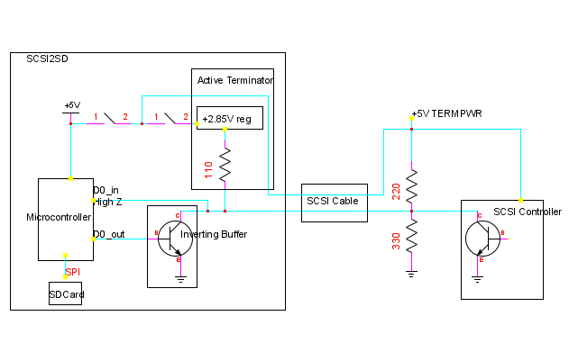
- Direct connection of the SCSI wires to a microcontroller is not possible, as micros generally have 3-state GPIO pins. It could be possible to simulate an open collector output by switching between output/low states and input states, however...
- Direct connection of the SCSI wires to a microcontroller is not possible, as most micros cannot sink enough current when output is in the low state.
Consider the current required when the low output is pulled up with 1 passive and 1 active terminator- the micro would have to sink (5/220 + 2.85/110) = 49mA.
The NXP LPC Arm controllers can only sink 4mA per pin.
The SCSI signal levels are TTL compatible, as follows. Note that we never output a the high signals directly; the open-collector outputs become high-impedance, and the terminators bring the signal up to the required voltage.
| Asserted (true) | Released (false) | |
|---|---|---|
| Output | 0V to 0.5V |
2.5V to 5.25V |
| Input | 0V to 0.8V | 2V to 5.25V |
'
Multiple output buffer IC's will be used to overcome sinking current limitations. Each IC has a limit on the overall current output by the ground pin; using multiple buffers instead of 16bit/octal buffers helps to overcome this limitation.
Implementation Detail
- SCSI2SD Schematic Notes
- First reflow soldering attempt (build attempt 1)
Links
Projects
- AVR based SCSI RAM disk (Open-source AVR microcontroller SCSI interface)
- LUFA Open-source AVR microcontroller USB stack.
- SCSI parity generator
References
- Interface Circuits for SCSI Design Notes
- [2] IC logic families and typical propagation delays.
- AN-753 Simple Byte Parity Applications Featuring the FAST, 74F899